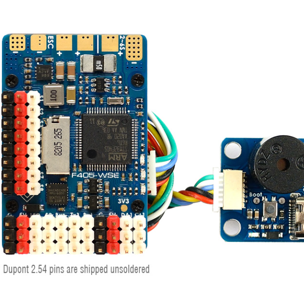


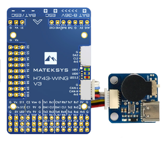
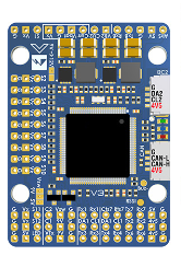
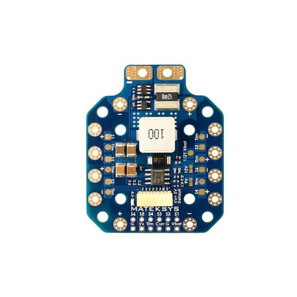
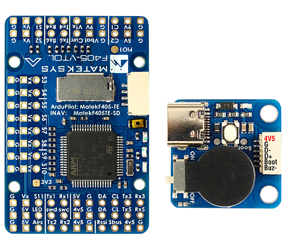
Description
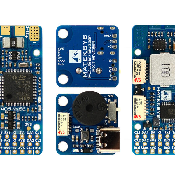
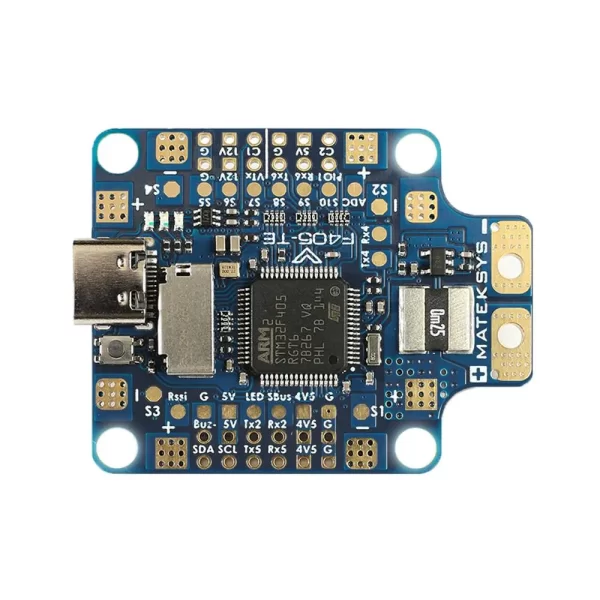
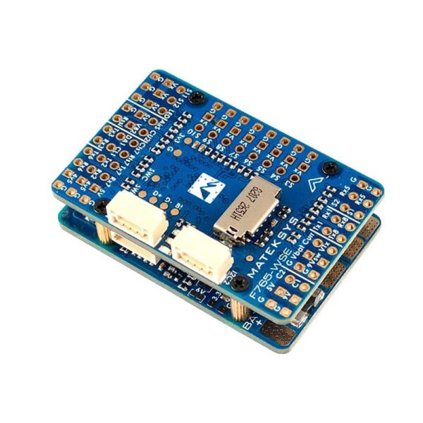
FLIGHT CONTROLLER F765-WSE
FC Specifications
- MCU: STM32F765VIH6, 216MHz , 512KB RAM, 2MB Flash
- IMU: ICM42688-P (SPI4)
- Baro: DPS310 (I2C2)
- OSD: AT7456E (SPI2)
- Blackbox: MicroSD card slot (SDIO)
- 6.5x Uarts (1,2,3,Rx5,6,7,8) with built-in inversion.
- 1x Softserial1_Tx (INAV)
- 12x PWM outputs (S1~S10 support Dshot)
- 6x ADC (VBAT, Current, RSSI, Analog AirSpeed, VB2, CU2)
- 3x LEDs for FC STATUS (Blue, Red) and 3.3V indicator(Red)
- 2x I2C
- 1x CAN
- USB/Beep Extender with Type-C(USB2.0)
- Dual Camera Inputs switch
- 9V(12V) for VTX power switch
- High-precision Current Sense, 220A range
- ADC VB2 voltage divider: 1K:20K
- ADC AirSpeed voltage divider: 20K:20K
- Static power 160mA@5V
FC Firmware
- INAV: MATEKF765SE
- ArduPilot: MATEKF765SE
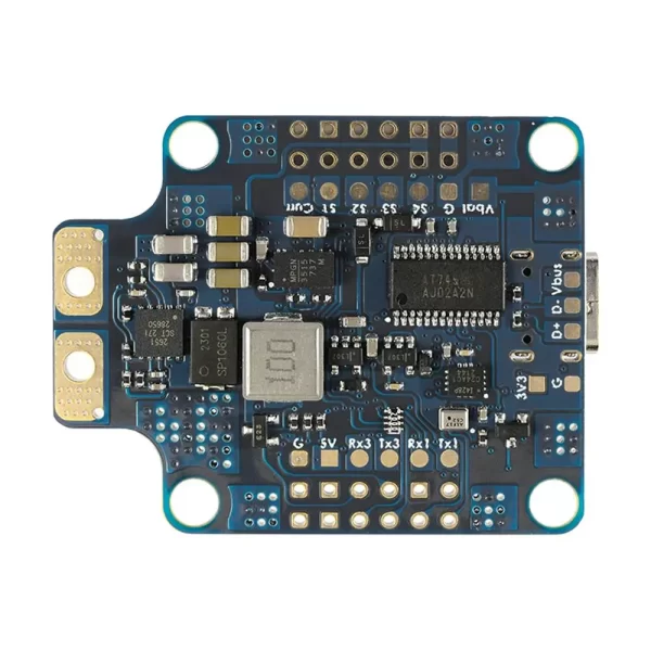
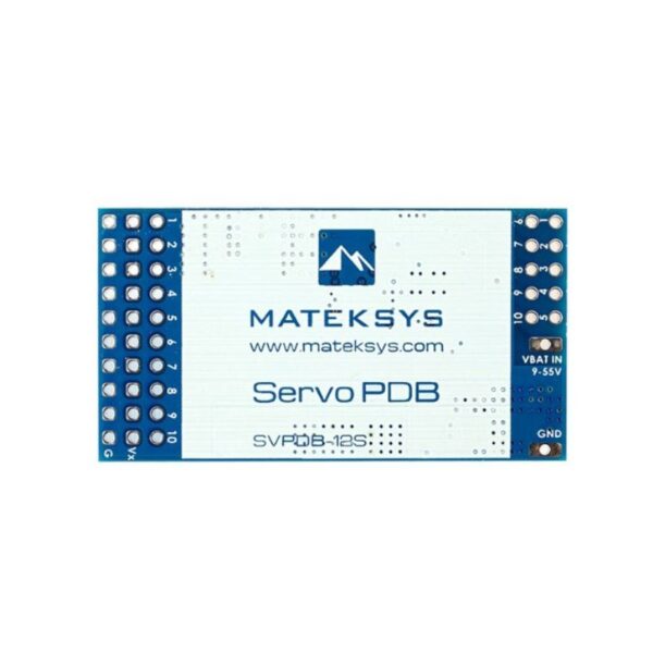
PDB
- Input voltage range: 6.8~30V (2~6S LiPo)
- 1x ESC power pads
- Battery Voltage divider 1K:20K (Scale 2100 in INAV, BATT_VOLT_MULT 21.0 in ArduPilot)
- Current Senor: 220A, 3.3V ADC (Scale 150 in INAV, 66.7 A/V in ArduPilot)
- Sense resistor: 90A continuous, 220A peak
BEC 5V output
- Designed for Flight controller, Receiver, OSD, Camera, Buzzer, 2812 LED_Strip, Buzzer, GPS module, AirSpeed
- Continuous current: 2 Amps, Max.3A
BEC 9V /12V output
- Designed for Video Transmitter, Camera, Gimbal ect.
- Continuous current: 2 Amps, Max.3A
- 12V option with Jumper pad
- for stable 9V/12V output, input voltage should > output voltage +1V
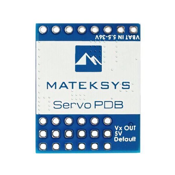
BEC Vx output
- Designed for Servos
- Voltage adjustable, 5V Default, 6V or 7.2V via jumper
- Continuous current: 8 Amps, Max.10A
- for stable Vx output, input voltage should > Vx voltage +1V
BEC 3.3V output
- Designed for Baro / Compass module and external 3.3V peripherals
- Linear Regulator
- Continuous current: 200mA
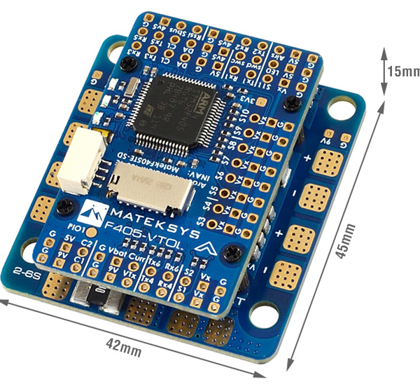
Physical
- Mounting: 25 x 25mm, Φ2mm
- Dimensions: 44 x 29 x 14.5 mm
- Weight: 22g w/ USB/buzzer adapter
Including
- 1x F765-WSE
- 1x USB(Type-C)/Beep (Passive buzzer) Extender
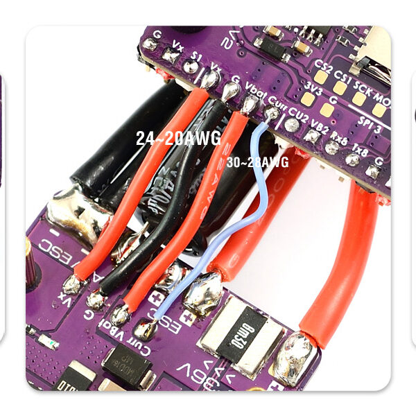
- 2x 20cm JST-GH-4P to JST-GH-4P cable for CAN & I2C port
- 1x 20cm JST-SH-6P to JST-SH-6P cable for USB extender.
- 1x Rubycon ZLH 35V 470uF capacitor
- Dupont 2.54 pins (Board is shipped unsoldered)
INAV MAPPING
| INAV | |||||
| PWM | S1 | PA0 | 5 V tolerant I/O | TIM2_CH1 | Fixed Wing Motor |
| S2 | PA1 | 5 V tolerant I/O | TIM2_CH2 | ||
| S3 | PA2 | 5 V tolerant I/O | TIM5_CH3 | Fixed Wing Servo | |
| S4 | PA3 | 5 V tolerant I/O | TIM5_CH4 | ||
| S5 | PB0 | 5 V tolerant I/O | TIM3_CH3 | ||
| S6 | PB1 | 5 V tolerant I/O | TIM3_CH4 | ||
| S7 | PD12 | 5 V tolerant I/O | TIM4_CH1 | ||
| S8 | PD13 | 5 V tolerant I/O | TIM4_CH2 | ||
| S9 | PD14 | 5 V tolerant I/O | TIM4_CH3 | ||
| S10 | PD15 | 5 V tolerant I/O | TIM4_CH4 | ||
| S11 | PE5 | 5 V tolerant I/O | TIM9_CH1 | ||
| S12 | PE6 | 5 V tolerant I/O | TIM9_CH2 | ||
| LED | PA8 | 5 V tolerant I/O | TIM1_CH1 | 2812LED | |
| ADC | Vbat pad 1K:20K divider builtin |
PC2 | 0~36V on F765-WSE |
Vbat ADC ADC_CHANNEL_1 |
scale 2100 |
| Curr Pad | PC3 | 0~3.3V | Current ADC ADC_CHANNEL_2 |
scale 150 | |
| RSSI Pad | PC1 | 0~3.3V | RSSI ADC ADC_CHANNEL_3 |
Analog RSSI | |
| AirS Pad 20K:20K divider builtin |
PC0 | 0~6.6V | AirS ADC ADC_CHANNEL_4 |
Analog Airspeed | |
| VB2 Pad 1K:20K divider builtin |
PA4 | 0~69V | ADC_CHANNEL_5 | scale 2100 | |
| CU2 Pad | PC5 | 0~3.3V | ADC_CHANNEL_6 | spare | |
| I2C | I2C1 CL1/DA1 |
PB6/PB7 | 5 V tolerant I/O | Compass | QMC5883 / HMC5883 IST8310 / IST8308 MAG3110 / LIS3MDL |
| OLED | 0.96″ | ||||
| I2C2 CL2/DA2 |
PB10/PB11 | 5 V tolerant I/O | onboard Barometer | DPS310 | |
| Digital Airspeed sensor | MS4525 | ||||
| Temperature sensor | |||||
| UART | USB | PA11/PA12 | 5 V tolerant I/O | USB | |
| TX1 RX1 | PA9/PA10 | 5 V tolerant I/O | USART1 | USER | |
| TX2 RX2 | PD5/PD6 | 5 V tolerant I/O | USART2 | USER | |
| TX3 RX3 | PD8/PD9 | 5 V tolerant I/O | USART3 | USER | |
| RX5 | PB8 | 5 V tolerant I/O | UART5 | USER | |
| TX6 RX6 | PC6/PC7 | 5 V tolerant I/O | UART6_RX | PPM & Serial RX | |
| UART6_TX | FPORT/SRXL | ||||
| RX7 TX7 | PE7/PE8 | 3.3 V tolerant I/O | UART7 | USER | |
| TX8 RX8 | PE1/PE0 | 5 V tolerant I/O | UART8 | USER | |
ARDUPILOT MAPPING
| ArduPilot | ||||||
| PWM | S1 | PA0 | 5 V tolerant I/O | PWM1 GPIO50 | TIM2_CH1 | Group1 |
| S2 | PA1 | 5 V tolerant I/O | PWM2 GPIO51 | TIM2_CH2 | ||
| S3 | PA2 | 5 V tolerant I/O | PWM3 GPIO52 | TIM5_CH3 | Group2 | |
| S4 | PA3 | 5 V tolerant I/O | PWM4 GPIO53 | TIM5_CH4 | ||
| S5 | PB0 | 5 V tolerant I/O | PWM5 GPIO54 | TIM8_CH2N | Group3 | |
| S6 | PB1 | 5 V tolerant I/O | PWM6 GPIO55 | TIM8_CH3N | ||
| S7 | PD12 | 5 V tolerant I/O | PWM7 GPIO56 | TIM4_CH1 | Gourp4 | |
| S8 | PD13 | 5 V tolerant I/O | PWM8 GPIO57 | TIM4_CH2 | ||
| S9 | PD14 | 5 V tolerant I/O | PWM9 GPIO58 | TIM4_CH3 | ||
| S10 | PD15 | 5 V tolerant I/O | PWM10 GPIO59 | TIM4_CH4 | ||
| S11 | PE5 | 5 V tolerant I/O | PWM11 GPIO60 | TIM9_CH1 | Group5 No DMA |
|
| S12 | PE6 | 5 V tolerant I/O | PWM12 GPIO61 | TIM9_CH2 | ||
| LED | PA8 | 5 V tolerant I/O | PWM13 GPIO62 | TIM1_CH1 | Group6 | |
| SERVO13_FUNCTION 120, NTF_LED_TYPES neopixel | ||||||
| PWM1~PWM13 are Dshot and PWM capable. However, mixing Dshot and normal PWM operation for outputs is restricted into groups, ie. enabling Dshot for an output in a group requires that ALL outputs in that group be configured and used as Dshot, rather than PWM outputs. If servo and motor are mixed in same group, make sure this group run lowest PWM frequency according to the servo specification. ie. Servo supports Max. 50Hz, ESC must run at 50Hz in this group. |
||||||
| ADC | Vbat Pad 1K:20K divider builtin |
PC2 | 0~36V on F765-WSE |
Vbat ADC onboard battery voltage sense |
BATT_VOLT_PIN BATT_VOLT_MULT |
12 21.0 |
| Curr pad | PC3 | 0~3.3V | Current ADC onboard current sense |
BATT_CURR_PIN BATT_AMP_PERVLT |
13 66.7 |
|
| VB2 Pad 1K:20K divider builtin |
PA4 | 0~69V | Vbat2 ADC | BATT2_VOLT_PIN BATT2_VOLT_MULT |
4 21.0 |
|
| CU2 Pad | PC5 | 0~3.3V | Current2 ADC | BATT2_CURR_PIN BATT2_AMP_PERVLT |
15 / |
|
| RSSI Pad | PC1 | 0~3.3V | RSSI ADC Analog RSSI |
RSSI_ANA_PIN RSSI_TYPE |
11 1 |
|
| AirS Pad 20K:20K divider builtin |
PC0 | 0~6.6V | AirS ADC Analog Airspeed |
ARSPD_PIN ARSPD_TYPE |
10 2 |
|
| I2C | I2C1 CL1/DA1 |
PB6/PB7 | 5 V tolerant I/O | Compass | COMPASS_AUTODEC | 1 |
| I2C2 CL2/DA2 |
PB10/PB11 | 5 V tolerant I/O | onboard Baro DPS310 | Address | 0x76 | |
| Digital Airspeed I2C MS4525 DLVR-L10D |
ARSPD_BUS ARSPD_TYPE ARSPD_TYPE |
1 1 9 |
||||
| CAN | CAN1 | PD0/PD1 | 5 V tolerant I/O | CAN Node | CAN_D1_PROTOCOL CAN_P1_DRIVER |
1 1 |
| CAN GPS CAN Compass CAN Airspeed sensor |
GPS_TYPE COMPASS_TYPEMASK ARSPD_TYPE |
9 0 8 |
||||
| UART | USB | PA11/PA12 | 5 V tolerant I/O | USB | console | SERIAL0 |
| RX7 TX7 RTS7 CTS7 | PE7/8/9/10 | 5 V tolerant I/O | UART7 | telem1 | SERIAL1 | |
| TX1 RX1 | PA9/PA10 | 5 V tolerant I/O | USART1 | telem2 | SERIAL2 | |
| TX2 RX2 | PD5/PD6 | 5 V tolerant I/O | USART2 | GPS1 | SERIAL3 | |
| TX3 RX3 | PD8/PD9 | 5 V tolerant I/O | USART3 | GPS2 | SERIAL4 | |
| TX8 RX8 | PE1/PE0 | 5 V tolerant I/O | UART8 | USER | SERIAL5 | |
| TX6 RX6 | PC6/PC7 | 5 V tolerant I/O | USART6 | RC input/Receiver | SERIAL7 | |
| RX6 | SBUS/IBUS/DSM/PPM | |||||
| TX6 | SRXL2 | |||||
| RX5 | PB8 | 5 V tolerant I/O | UART5 | USER | SERIAL8 | |
ARDUPILOT RELAY (PINIO)
- Camera-1 and 9Vsw On by default
- Make sure 2 cameras are set with identical video format, both PAL or both NTSC.
# GPIOs
- PE4 PINIO1 OUTPUT GPIO(81) //9Vsw pad power switch
- PE15 PINIO2 OUTPUT GPIO(82) //Camera switch
# RCx_OPTION: RC input option
- 28 Relay On/Off
- 34 Relay2 On/Off
- 35 Relay3 On/Off
- 36 Relay4 On/Off
e.g.
- RELAY_PIN 81 //9Vsw GPIO
- RC7_OPTION 28 //Relay On/Off, Use CH7 of Transmitter to switch Vsw
- RELAY_PIN2 82 //Camera switch GPIO
- RC8_OPTION 34 //Relay2 On/Off, Use CH8 of Transmitter to switch camera
or
- RELAY_PIN3 81 //9Vsw GPIO
- RC9_OPTION 35 //Relay3 On/Off, Use CH9 of Transmitter to switch Vsw
- RELAY_PIN4 82 //Camera switch GPIO
- RC10_OPTION 36 //Relay4 On/Off, Use CH10 of Transmitter to switch camera
The configured feature will be triggered when the auxiliary switch’s pwm value becomes higher than 1800. It will be deactivated when the value falls below 1200.
Check the pwm value sent from the transmitter when the switch is high and low using the Mission Planner’s Initial Setup >> Mandatory Hardware >> Radio Calibration screen. If it does not climb higher than 1800 or lower than 1200, it is best to adjust the servo end points in the transmitter.
NOTES & TIPS
Supported by ArduPilot latest or beta release 4.1.x or higher
New Gyro ICM-42605/42688-p has been supported by INAV 3.0.2, you might download INAV fw 3.0.2 from configurator.
- ICM-42605/42688-p has not been listed in configurator 3.0.1 – configuration – Accelerometer, if you type CLI command “get acc_hardware”, ICM42605 is available.

dixitad88 (verified owner) –
Mighty product. Size, build quality & many more other features in such tiny FC.
Upvote if this was helpful (0) Downvote if this was not helpful (0) Watch Unwatch Flag for removal