

Description
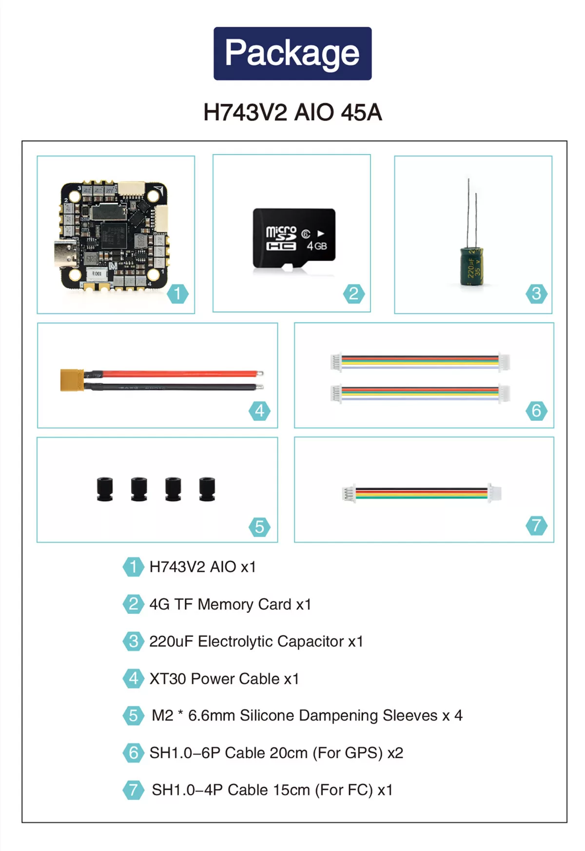
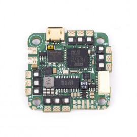
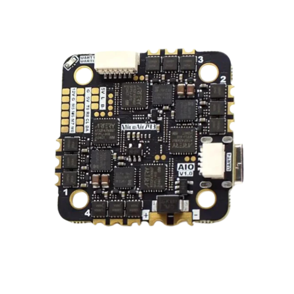
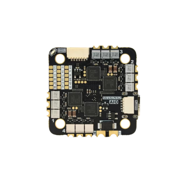
MicoAir743v2-AIO-45A
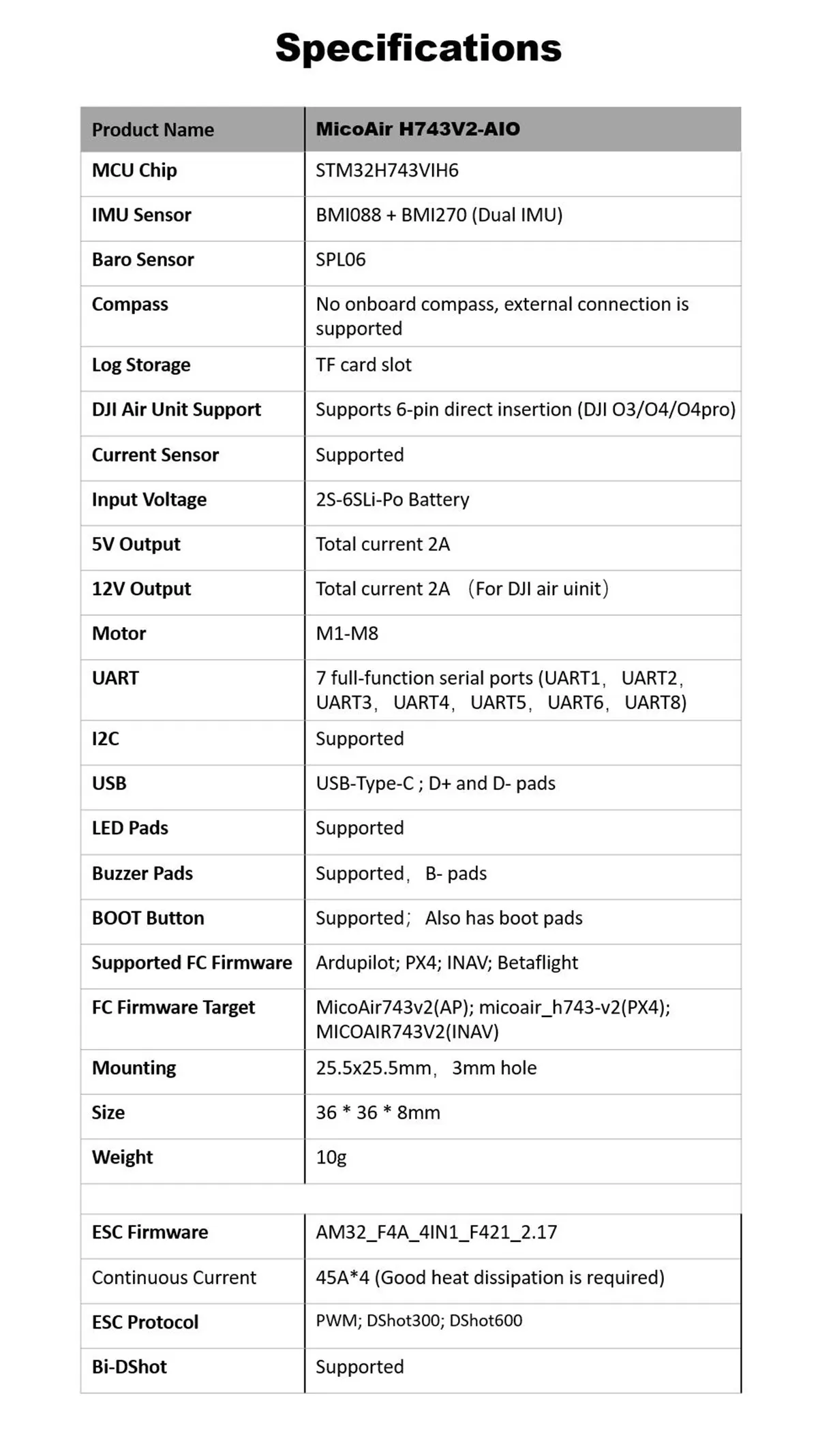
SPECIFICAIONS:
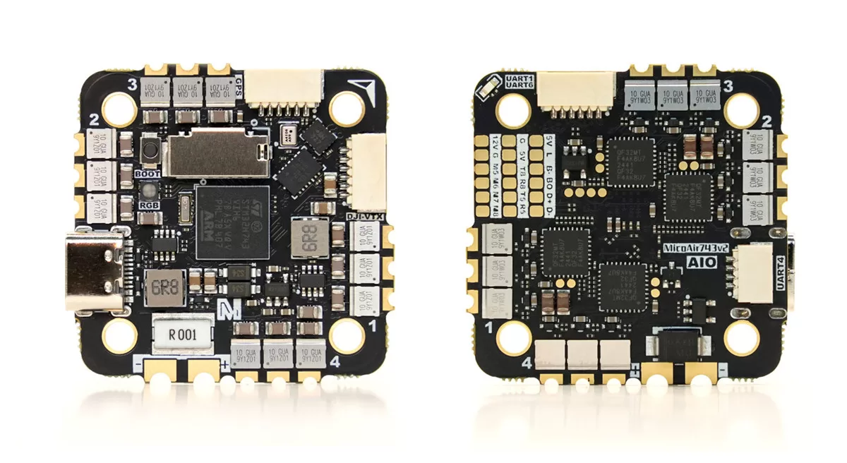
Flight Controller
- MCU: STM32H743VIH6, 480MHz, 2MB Flash
- IMU: BMI088+BMI270
- Baro: SPL06
- TF Card Slot
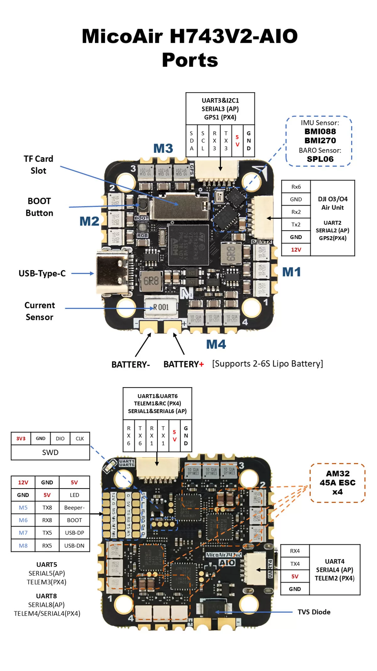
- 7x UART
- 9x PWM
- 1x I2C
- 1x SWD
- 2x ADC (VBAT, Current)
- 1x LED Strip
- 1x Beeper
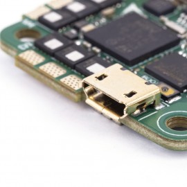
- USB Type-C
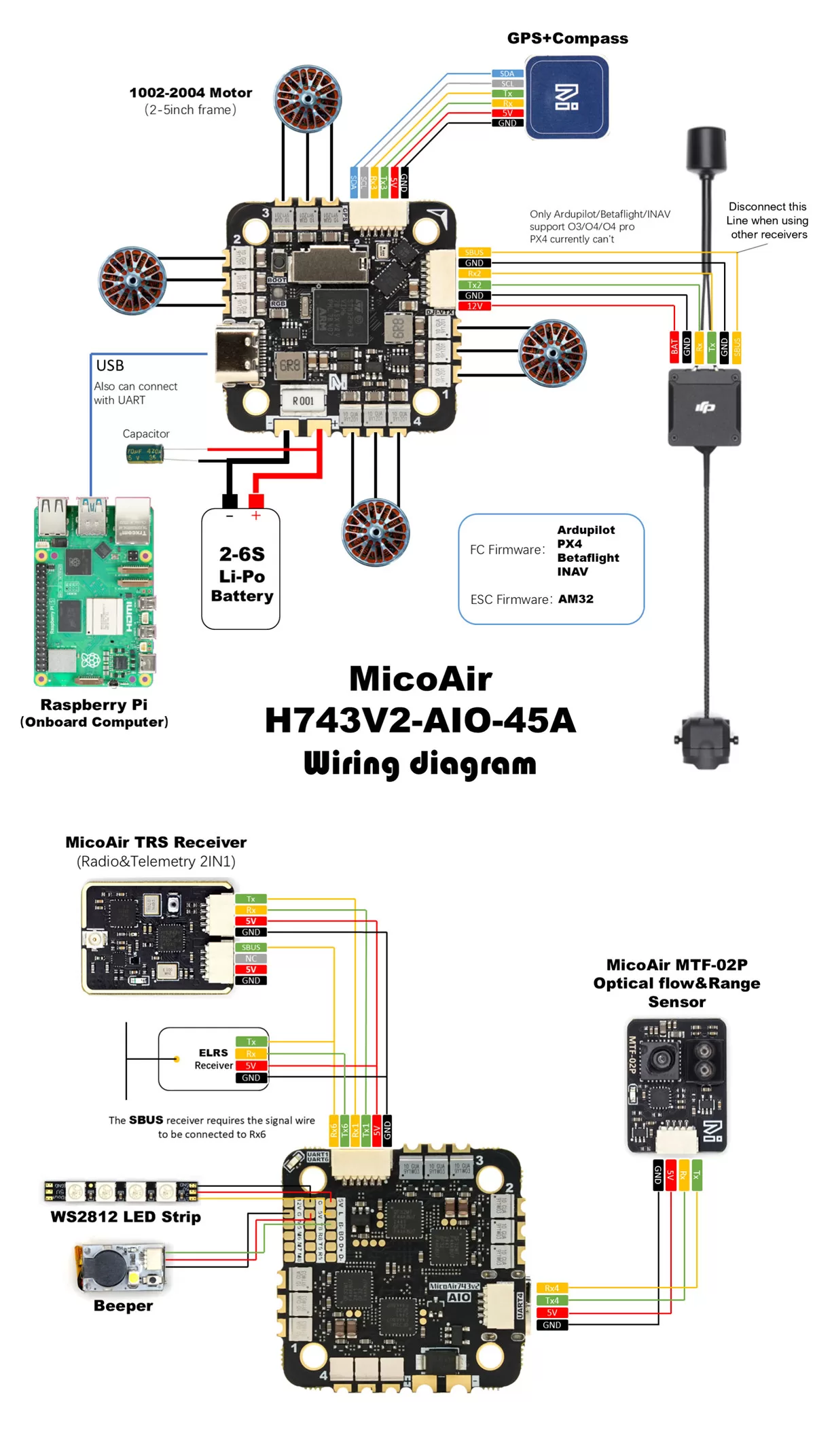
- BEC 5V 2A output (for controller, receiver, GPS, optical flow or other devices)
- BEC 12V 2A output (for DJI O3/O4/O4 pro)
ESC
- Firmware: AM32_F4A_4IN1_F421_2.17
- PWM Freq: 48KHz
- ESC Protocol: PWM/DShot300/DShot600 (support BDShot)
- Continuous Current: 45A * 4
- Voltage Support: 2-6S (5.6V-27V)
Tutorial: How to Configure and Update AM32 ESC on MicoAir743-AIO
Voltage&Current Monitoring
| Ardupilot | PX4 | Betaflight | INAV | |
| Voltage Factor | 21.12 | 21.12 | 211 | 211 |
| Current Factor | 14.14 | 14.14 | 707 | 707 |
UART Mapping (Ardupilot)
- SERIAL0 -> USB
- SERIAL1 -> UART1 (MAVLink2, DMA-enabled)
- SERIAL2 -> UART2 (DisplayPort, DMA-enabled)
- SERIAL3 -> UART3 (GPS, DMA-enabled)
- SERIAL4 -> UART4 (MAVLink2, DMA-enabled)
- SERIAL5 -> UART5 (DMA-enabled)
- SERIAL6 -> UART6 (RCIN, DMA–enabled)
- SERIAL8 -> UART8 (DMA–enabled)
UART Mapping (PX4)
- ttyACM0->USB
- ttyS0->TELEM1 -> UART1
- ttyS1->GPS2 -> UART2
- ttyS2->GPS1 -> UART3
- ttyS3->TELEM2 -> UART4
- ttyS4->TELEM3-> UART5
- ttyS5->RC -> UART6
- ttyS7->TELEM4/SERIAL4 -> UART8
RC Input (Ardupilot)
The default RC input is configured on the UART6. The SBUS pin is inverted and connected to RX6. Non SBUS, single wire serial inputs can be directly tied to RX6 if SBUS pin is left unconnected. RC could be applied instead at a different UART port such as UART2, UART4 or UART8, and set the protocol to receive RC data: SERIALn_PROTOCOL=23 and change SERIAL6 _Protocol to something other than
23.OSD Support (Ardupilot)
The MicoAir743v2-AIO supports OSD using OSD_TYPE 5 (MSP_DISPLAYPORT).
VTX Support
The SH1.0-6P connector supports a DJI Air Unit / HD VTX connection. Protocol defaults to DisplayPort. Pin 1 of the connector is 12v so be careful not to connect this to a peripheral requiring 5v.
PWM Output
The MicoAir743v2-AIO supports up to 9 PWM outputs.
Channels 1-8 support DShot/bi-directional DShot.
(currently PX4&INAV not support BDShot function)
PWM output share grouped and every group must use the same output protocol:
1,2,3,4 are group 1
5, 6 are group 2
7,8, 11are group 3
Note: PWM11 is the “LED” pin. If this is configured for serial LED use then PWM 7 and 8 can only be used as serial LED also.
Compass
The MicoAir743v2-AIO doesn’t have a built-in compass sensor, but you can attach an external compass using I2C on the SDA and SCL connector.
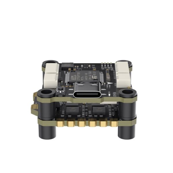
Physical
- Mounting: 25.5 x 25.5mm, Φ3mm
- Dimensions: 36 x 36 x 8 mm
- Weight: 10g
Related-links
- Mission Planner
- QGround Control
- ArduPilot Documentation
- PX4 Documentation
- Betaflight Configurator
- INAV Configurator
PINOUTS:
| STM32H743VIH6 | ||||
|---|---|---|---|---|
| IMU | BMI270 | SPI3 | MOSI | PD6 |
| MISO | PB4 | |||
| SCLK | PB3 | |||
| BMI270_CS | PA15 | |||
| GPIO | BMI270_DR | PB7 | ||
| BMI088 | SPI2 | MOSI | PC3 | |
| MISO | PC2 | |||
| SCLK | PD3 | |||
| BMI088_GYRO_CS | PD5 | |||
| BMI088_ACCEL_CS | PD4 | |||
| GPIO | BMI088_GYRO_DR | PC15 | ||
| BMI088_ACCEL_DR | PC14 | |||
| Barometer | SPL06 | I2C2 | SCL | PB10 |
| SDA | PB11 | |||
| GPIO | SPL06_DR | PD0 | ||
| Motor | PWM | TIM1/CH4 | M1 | PE14 |
| TIM1/CH3 | M2 | PE13 | ||
| TIM1/CH2 | M3 | PE11 | ||
| TIM1/CH1 | M4 | PE9 | ||
| TIM3/CH4 | M5 | PB1 | ||
| TIM3/CH3 | M6 | PB0 | ||
| TIM4/CH1 | M7 | PD12 | ||
| TIM4/CH2 | M8 | PD13 | ||
| LED Strip | PWM | TIM4/CH3 | PD14 | |
| Buzzer- | GPIO | PD15 | ||
| OSC | external | 8MHz | OSC_IN | PH0 |
| OSC_OUT | PH1 | |||
| LED | GPIO_OUTPUT | RED | PE3 | |
| BLUE | PE4 | |||
| GREEN | PE2 | |||
| KEY | BOOT | BOOT0 | ||
| I2C | I2C1 | SDA | PB9 | |
| SCL | PB8 | |||
| UART | UART1 | TX | PA9 | |
| RX | PA10 | |||
| VTX-HD | UART2 | TX | PA2 | |
| RX | PA3 | |||
| GPS | UART3 | TX | PD8 | |
| RX | PD9 | |||
| UART4 | TX | PA0 | ||
| RX | PA1 | |||
| UART5 | TX | PB6 | ||
| RX | PB5 | |||
| RCIN | UART6 | TX | PC6 | |
| RX | PC7 | |||
| Bluetooth Telemetry | UART8 | TX | PE1 | |
| RX | PE0 | |||
| USB | USB | USB_DM | PA11 | |
| USB_DP | PA12 | |||
| SD Card | SDMMC1 | D0 | PC8 | |
| D1 | PC9 | |||
| D2 | PC10 | |||
| D3 | PC11 | |||
| CLK | PC12 | |||
| CMD | PD2 | |||
| DEBUG | SWD | SWDIO | PA13 | |
| SWCLK | PA14 | |||
| BATTERY | (Ratio 1:21) | ADC | Voltage | PC0 |
| Current | PC1 | |||